Question 3
Plan view of a steel portal frame building is shown in Figure 3. Roof layers (roof sheeting, insulation and roof bracing) are supported by purlins which are in turn supported by four universal beams. The roof has two internal span (X and Y) and a cantilever span of X/4.
a) Develop line load diagrams showing the critical strength design load combination of permanent and imposed actions for the following members:
(i) A typical purlin
(ii) Beam B1-2 and beam B3-4
b) Determine the design loads applied to columns C1, C2 and C3.
Roof sheeting self-weight allowance = 5.1 kg/m2; self-weight of insulation and roof bracing = 0.062 kPa. For self-weights of purlins (Z15024) and beams (360UB56.7) see Lysaght and OneSteel catalogues. Use Table 3.2 of AS/NZS 1170.1 to determine imposed action (only uniformly distributed actions is required in this assignment- ignoring concentrated actions).
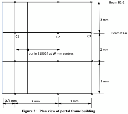
Your personal design data (W, X, Y, Z):
Use the last three digits of your student ID, denoted ‘xyz' to work out these four parameters as follows: W (mm) = 1150+x*10; X (mm) = 6000 + y*10; Y (mm) = 5000+ y*10; Z (mm) = 5300+ 7*10. The cantilever span (X/4) is to round down to the nearest of 10 mm.
For instance, a student has an ID of 0123456 will have ‘xyz' = 456 and therefore W = 1150 +4*10= 1190 mm; X = 6000 + 5*10= 6050 mm; Y = 5000 + 5*10 = 5050 mm; Z= 5300 + 6*10 = 5360 mm. The cantilever span=X/4 = 6050/4 = 1512.5 and thus = 1510 mm after rounding down to the nearest of 10mm
Students succeed in their courses by connecting and communicating with an expert until they receive help on their questions

Consult our trusted tutors.


 Login | Sign Up

