Part II. Logical Database Design
Read a case study for “A Small Private Airport Database” attached.
The figure below shows an EER diagram for the database.
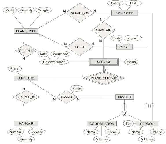
3. Transform this EER-diagram into relational schemas.
In the relational database schema, clearly show all entity integrity constraints, and if any, referential integrity constraints, that is,
- Clearly indicate the primary key (PK) of each relation.
- If any, denote the foreign keys (e.g., FK, FK1, K2). For example, Use FK for one foreign key. If the relation has multiple foreign key, use FK1, FK2, … If the relation has a composite foreign key in columns C1, and C2. Use a same foreign key notation, e.g., FK in C1 and FK in C2, or FK1 in C1 and FK1 in C2. To indicate the table referenced by a foreign key, use an arrow line.
- The domain constraint (e.g., data type, data length) of each attribute is not required.
You can use any drawing tool or database modeling tool (e.g., ERwin, Rational Rose). For example, MS Visio supports relational schema notations. Use an arrow line to indicate the table referenced by a foreign key.
Students succeed in their courses by connecting and communicating with an expert until they receive help on their questions

Consult our trusted tutors.


 Login | Sign Up

