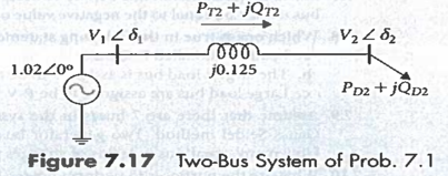
7.1. For the two-bus system in Figure 7.17, Pr2 + jQT2 = 1.1 + j0.4, all numerical values are in per unit. Perform two iterations of Gauss-Seidel power-flow method to find voltage magnitude and angle at bus 2. Assume that bus 1 is the slack bus and the initial voltage at bus 2 is 1.0∠0°
7.3. In Example 7.8, suppose that the generator's maximum reactive power generation at bus is limited to 125 Mvar. Recompute the first-iteration value of the voltage at bus using the Gauss-Seidel method.
7.4. For the system of Figure 7.5, complete the second iteration of the Gauss-Seidel procedure using the first-iteration bus voltages obtained in Examples 7.7 and 7.8. Assume an acceleration factor of 1.6.
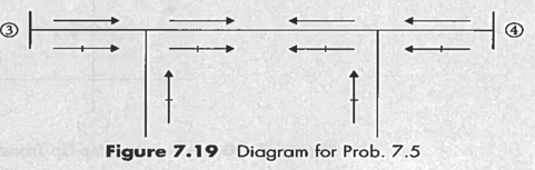
7.5. Take Figure 7.19 as the equivalent-representation of the transmission line between bus and bus of the system of Figure 7.5. Using the power-flow solution given in Figure 7.7, determine and indicate on Figure 7.19 the values of (a) P and Q leaving buses and on line - (b) charging megavars of the equivalent π of line 3-4, and (c) Pand Q at both ends of the series part of the equivalent π of line 3- 4.
7.6. From the line flow information of the power-flow solution given in Figure 7.7, determine I'R loss in each of the four transmission lines, and verify that the sum of these line losses is equal to the total system loss of 4.81 MW.
Students succeed in their courses by connecting and communicating with an expert until they receive help on their questions

Consult our trusted tutors.


 Login | Sign Up

