II. Technical Drawing.
1. Create the model of the cover as shown in Figure 1-1.
2. Create the model of the cover as shown in Figure 2-1.
3. Create the model of the cover as shown in Figure 3-1.
II. Technical Drawing.
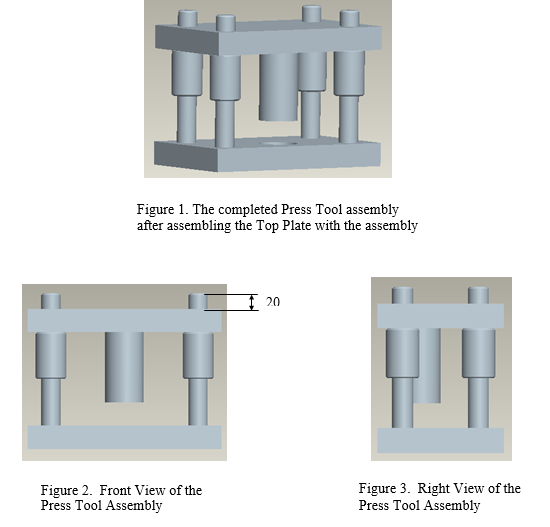
1. Please create the Press Tool assembly shown in Figure 1.
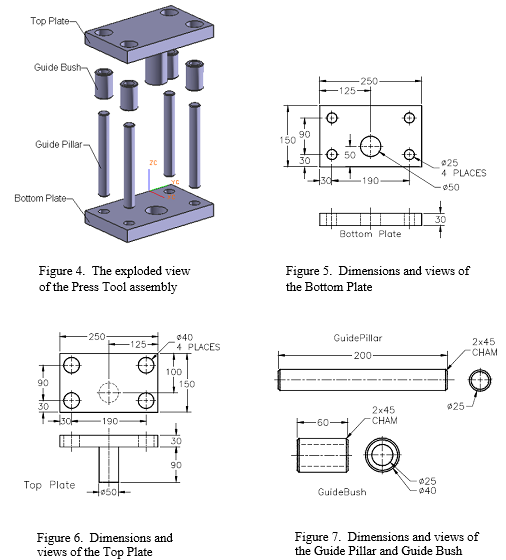
The front and right views of the Press Tool assembly are shown in Figure 2 and 3. The exploded state of the assembly is shown in Figure 4 and the dimensions of the components of the Press Tool assembly are shown in Figures 5 through 7.
2. Create an exploded state of the assembly in the assembly mode.
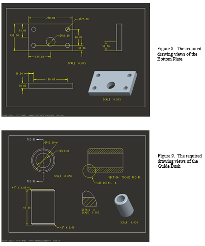
3. Generate the drawing views with dimensions of the Bottom Plate and the Guide Bush on A4 size sheet, as shown in Figure 8 and Figure 9.
a. Bottom Plate- including top view, front view, right view and isometric view.
b. Guide Bush- including top view, front view, sectioned right view, detailed view of chamfer and isometric view.
Students succeed in their courses by connecting and communicating with an expert until they receive help on their questions

Consult our trusted tutors.


 Login | Sign Up

