Question:
Performance data for a WaterFurnace Envision NXW Reversible Chiller, Model 120, has been excerpted below. (The full submittal set is in the HW module, file name:
Water Furnace Envision NXW Rev Chiller Submittal Set.pdf).
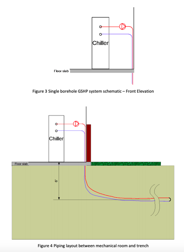
The full submittal set also contains details of where the piping is connected as well as the inlet and outlet pipe size. (See pages 5 and 6 of the submittal set; the ground loop is connected to the source side.) The chiller is set at grade level 2' from the edge of the building inside a mechanical room, as shown in Figures 2 and 3. The piping is 2" SDR-11 HDPE. The design flow rate is 20 GPM at a chiller entering fluid temperature of 90°F.
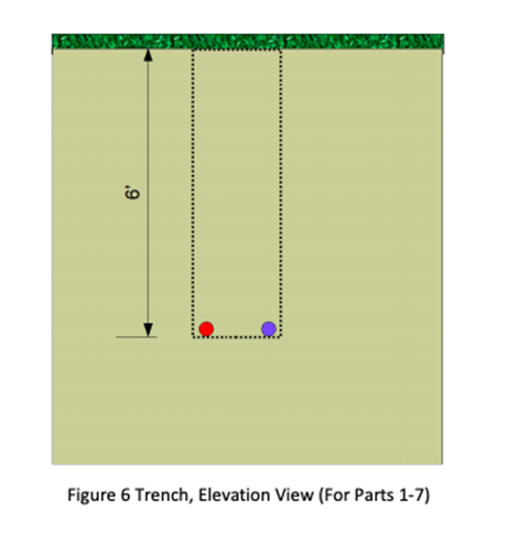
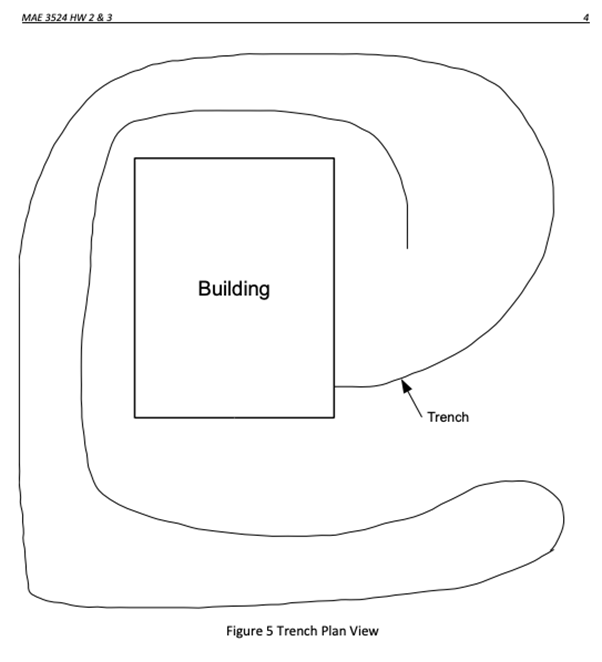
The ground heat exchanger for parts 1-7 consists of a single loop in a horizontal trench. As shown in Figure 4, the piping is simply bent in a large radius in order to transition from vertical to the horizonal trench. The trench is shown in Figure 5. The trench is about 1000' in length, such that the piping, from the floor of the mechanical room goes out 1000' and then returns. The outgoing and return pipes are approximately 16" apart in the trench. (To be clear, this is likely not enough ground heat exchanger to support the thermal loads.] The large radius bends have minimal impact on the pressure loss in the pipe, so you can treat the pipe as if it is straight.
1. Make a table showing all the fittings, their diameters, their equivalent lengths, and their head loss at the design flow rate. (Include the chiller, but you don't need to determine its equivalent length.) Determine the total head loss of the fittings.
2. Determine the total piping length and the total head loss of the straight pipe.
3. Determine the system head loss for conditions where the chiller entering fluid temperature is 90°F and the desired (design) flow rate is 20 GPM.
4. A set of pump curves for different Bell & Gossett A-120H pumps is shown in the file Bell_$_Gossett_1-1204.pdf in the class resources directory. Can one of these pumps work? If so, which one? Choose the pump that is sufficient but has the least amount of oversizing. If none of these pumps work find a pump that will work, give the full details including pump curves in your homework solution, and complete the assignment.
5. Plot the system curve, overlaying it on the pump curve. Show the design point and actual operating point. Label clearly.
6. What flow rate do you expect the system will operate at? Explain.
7. According to the manufacturer's data in the submittal set (Bell_4_Gossett_A-1208.pdf), what voltage, amperage, and actual power will the pump consume? (Some pumps come in two models, where one is single phase and has an "S" at the end of the model number, and the other is three-phase and has a "T" at the end of the model number. Please use single phase and 230V, if available, for your selected pump.) What horsepower is given? Are the watts equivalent to the stated horsepower?
8. By adding elbows and tees, and a second loop (as shown in Figures 7 & 8), the trench can be shortened significantly. The two loops are now made from 1 %" SDR-11 HDPE pipe and each one goes out 500' and back again.
a. Update your table from Part 1 to reflect the new fittings; add a column to show the flow rate through each fitting.
b. Determine the head loss in each horizontal loop.
c. Determine the head loss for the whole system.


Students succeed in their courses by connecting and communicating with an expert until they receive help on their questions

Consult our trusted tutors.