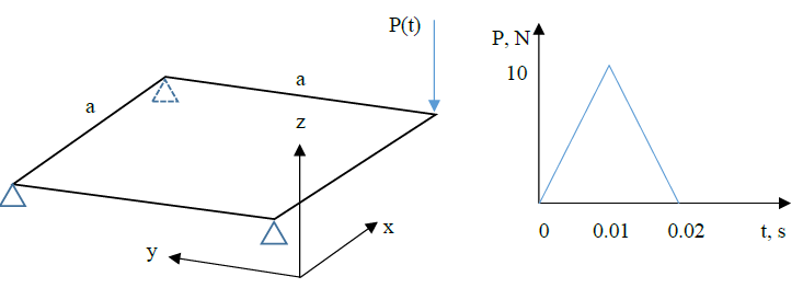
Using commercial FEA software package MSC Marc Mentat, model dynamic response of the plate shown below over 0.5 seconds. Compare results of direct transient and modal superposition analyses. Material properties of the plate: E=200 GPa, v=0.33, p=7890 kg/m3. Dimensions: side length a=1m, thickness t=0.003 m.
A. BACKGROUND INFORMATION
Modal superposition is a technique for reducing the computation time. Using this method, the dynamic response of a structure can be approximated by a superposition of a small number of its eigenmodes. Normally used for frequency analysis in the case of a harmonic loading, modal superposition can also be used for some transient problems.
B. SETTING UP
Start Marc Mentat, set the current directory to the folder “Lab08” and save the model as “lab08.mud”.
C. GEOMETRY AND MESH GENERATION
1. Change units to “m”.
2. Create 4 nodes with the coordinates of the corners of the plate, then a quad element based on the nodes. Subdivide the element into 20 in each direction. Sweep.
D. GEOMETRIC AND MATERIAL PROPERTIES
1. Create a geometric property for the plate (type “Structural 3D Shell”) with the given thickness value. Apply to all elements.
2. Create an isotropic elastic material property with the given Young’s modulus, Poisson’s ratio and mass density. Apply to all elements.
E. BOUNDARY CONDITIONS
1. Fix three out of four corners (all displacements AND all rotations).
2. Create a new table with 1 independent variable (time) and enter the following data points: 0 0 0.01 1 0.02 0 1 0. We need to specify that the force stays at zero all the way until the end of the analysis. Otherwise the program will extrapolate from the existing points.
3. Create a point load with the Z component equal to the max magnitude (see force vs time plot above) directed down. Select the previously created table (the max value will be multiplied by the table which is a function of time). Apply to the unconstrained corner.
F. LOADCASE AND JOB PROPERTIES
1. Create a new Dynamic Modal loadcase. Set “# Modes” to “20”. Rename the loadcase to “LCModal”.
2. Create a new Dynamic Transient loadcase. Set “Total Loadcase Time” to “0.5” and “# Steps” to “1000”. In Convergence Testing switch to “Displacements” and set tolerance to “0.01”. Rename the loadcase to “LCTransient”.
We will create two jobs: (1) direct transient analysis. The displacements in this case will be calculated from direct numerical integration discussed in class; (2) modal superposition. The dynamic response in this case is modeled as superposition of natural modes of vibration. The second type should be somewhat faster and be less sensitive to the time step (but sensitive to the number of modes selected in the “LCModal” loadcase).
3. Create a new “Structural” job and add “LCTransient” only. Rename this job to “Direct”.
4. Create another “Structural” job and add “LCModal” as the first and “LCTransient” as the second loadcases (order is important). In this job, first 20 natural modes and corresponding frequencies will be determined, then they will be used for dynamic transient analysis. Click on Modal Superposition in Analysis Options → Dynamic Transient Operator → Implicit. Rename this job to “ModalSuperposition”.
5. Run both jobs (one at a time), record the “Wall Time” for each. Which ran faster?
G. POSTPROCESSING
1. Examine the first 20 frames one by one (do not press play) in the results file of the “ModalSuperposition” job. Sub-increments 0:1 to 0:20 show the first 20 natural modes of vibration of the plate. The corresponding frequencies are shown in the top left corner. Play the rest of the animation.
2. Generate the “History Plot” of the Z component of displacement of the corner to which point force is applied. Do this for both jobs. Plot on the same chart in Excel.
3. Rerun both jobs with 200 time steps instead of 1000. Record run times. Repeat Step 2. Note: all 4 curves must be on the same chart.
4. How do “Direct” and “ModalSuperposition” results compare in the case of 1000 increments? In the case of 200 increments? Which is more accurate in the latter case, “Direct” or “ModalSuperposition”?
5. What about run times? Which is faster?
Students succeed in their courses by connecting and communicating with an expert until they receive help on their questions

Consult our trusted tutors.


 Login | Sign Up

