Q1.
Your friend wants to suspend a VW Golf (with curb weight of 1500kg) 10m off the ground outside their workshop on a single vertical column. As a graduate engineer, you are called upon to check their proposal. The plan is to roll 1mm sheet steel into a tube of 200mm OD and continuously spot weld along its length. The lower end will be concreted into the ground and a collar will be fixed at the top to transfer the weight of the car to the column evenly.
Part A
1. Using hand calculations, determine the cross-sectional area, moment of inertia and mass of the column. Assume that the density of the steel is 7850 kg/m³ and the Young’s modulus is 200 GPa.
2. Using the appropriate analytical model, determine the deflection at the top of the column due to the mass of the car. You may ignore the self-mass of the column.
3. Using an analytical equation, determine the critical load of the column based on Euler buckling theory. Comment on capacity of the column to support the mass of the car.
4. Using a finite element formulation with a two bar-elements, determine the deflection at the top of the column due to the mass of the car, either by a hand calculation or using Matlab. Compare your FE solution against the analytical solution.
5. Using a Static Structural ANSYS, build a model using 10 linear beam elements and calculate the deflection at the top of the column due to the mass of the car. You will need to define a line body and an appropriate cross-section. Pay close attention to how you define the column radius, and where the mid-plane of the wall resides. As a sanity check, compare against the parameters calculated in part A.1. Compare the deflection obtained using ANSYS against theory in A.2 and your hand calculation in A.4.
6. In ANSYS, drop an Eigenvalue Buckling analysis on to the solution of the Static Structural Analysis. Solve for the first 10 buckling modes. Determine the load multiplier for the first mode. Compare against the analytical solution in part A.3.
Note: The higher order modes will be compared against the modes in Part B below.
Part B
We will now repeat the exercise using thin shell elements in ANSYS. First you need to build the model. To do so open a new Static Structural analysis in the same Workbench project as Part A. Using DesignModeler or SpaceClaim build a surface body of the cylindrical column. Pay close attention to the mid-plane of the column. As a sanity check, compare against the parameters calculated in part A.1. In ANSYS Mechanical, mesh the body with quadratic quadrilateral shell elements using an element size of 25mm.
1. After applying the appropriate boundary conditions, determine the deflection at the top of the column due to the mass of the car. Compare against the answers obtained using theory in A.2, your hand calculation in A.4 and the static analysis from ANSYS in A.5.
2. In ANSYS, drop an Eigenvalue Buckling analysis on to the solution of the Static Structural Analysis for the shell model. Solve for the first 10 buckling modes. Determine the load multipliers. Compare against the first mode against the analytical solution in part A.3 and all the modes against the beam model in A.6.
3. Look at the higher order buckling modes and see if shell buckling is likely to be an issue. Comment on the veracity of this result.
Q2.
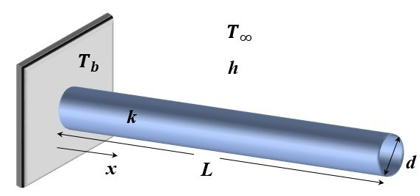
An air temperature probe may be analysed as a fin. Consider the geometry of the solid cylindrical probe shown below with the following parameters; a probe of length L = 20 mm, thermal conductivity of k = 19 W/mK, cylinder diameter d = 3 mm, an external convection coefficient of h = 50 W/m2K, an air temperature of T∞ = 50º C and the surface temperature at the base of the probe is Tb = 60º C.
1. Analytical Model: Using the appropriate 1D analytical model, determine the temperature of the tip of the probe and the heat flux from the base of the probe into the air. Account for convection from the side walls and the tip of the probe.
2. Hand calculation FEA: Using four 2-noded linear thermal elements, either by hand or using a Matlab script, determine the temperature and heat flux (as in question 1 above) using finite element analysis.
3. ANSYS 2D: Using ANSYS, determine the temperature and heat flux using a 2D axisymmetric model. In your answers include a figure showing your mesh and temperature profile of the solution.
4. ANSYS 3D: Using ANSYS, determine the temperature and heat flux using a 3D model. In your answers include a figure showing your mesh and temperature profile of the solution.
5. Compare the results of the temperature and heat flux obtained in questions (1) to (4). Reflect on the effort required to obtain the solution, both in terms of human resources and computing resources.
Hints: Question 3.
• To undertake a 2D analysis, in WB click on Geometry, then in the right-hand window under Properties > Advanced Geometry Options > 2D.
• Build the appropriate surface body in DesignModeler or SpaceClaim. Note that ANSYS assumes that the body is revolved around the y-axis.
• In WB > Tools > Options > Appearance > turn on Beta Options. This will permit you to visualise the 2D model as a 3D system.
• Do not forget to set the thermal conductivity of your material.
• Use an appropriate mesh with the knowledge you have developed in the course. You need to show the mesh in your solutions and you will be graded on the appropriateness of the mesh. Note the order of the elements you have used and their type (see Solution > Solution Information).
• In Mechanical > Model (A4) right click and add Symmetry. In the Details of Symmetry > Type > 2D Axisymmetric. You can select the delta angle. The default is 10 degrees which will give a slice every 36 degrees. You may set this value to 0 degrees to only show the 2D model. Note this is only for visualisation and is not needed for the calculation.
Hints: Question 4.
• Build a solid body in either DesignModeler or SpaceClaim. DesignModeler has convenient primitives (i.e. a cylinder).
• Use an appropriate mesh with the knowledge you have developed in the course. You need to show the mesh and you will be graded on the appropriateness of the mesh. Note the order of the elements you have used and their type (see Solution > Solution Information).
Question 1:
Using two 2-noded Euler-Bernoulli elements determine the critical buckling load. You may solve either by hand or using Matlab. See Assignment 2, 2019 for the procedure.
Question 2:
Using 1D thermal elements in ANSYS, determine the temperature of the probe tip and heat flux of the probe modelled in Question 2. This is not for the fainthearted!
Question 3:
Meshing is one of the most important stages of finite element analysis. With simple models and modern computing, it is often possible to use brute force to obtain mesh convergence. However, there is still value in knowing how to obtain accurate solutions with well-designed elegant meshes. Try and determine the minimum number of nodes and elements possible and still have 4 significant figure accuracy for the temperature of the tip. $25 cash for the individual who obtains the smallest node or element count – so there’s $50 on the table. Note that Ben Cazz has set the benchmark so you need to beat his models! John and Araz are also trying to earn $25 so there’s a bit of competition.
Students succeed in their courses by connecting and communicating with an expert until they receive help on their questions

Consult our trusted tutors.


 Login | Sign Up

