I. INTRODUCTION
You work within an engineering team developing autonomous driving for the worlds largest electric car manufacturer, Edison. Your boss has asked you to program and test, by simulation in the Keil IDE, a 20MHz C167 microcontroller for their new prototype car, the Model Γ. You will provide the Keil project and engineering report to your boss upon completion. The report describes your program with documentation of the implementation and a demonstration of the functionality.
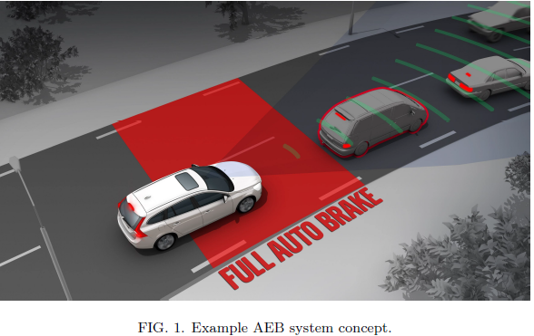
As part of an autonomous embedded system, your task is to design a specific sub-system to supply information to an emergency braking (AEB) controller. Primarily, the braking torque required to stop the vehicle before a collision. The AEB will either provide a warning to the driver or take complete control over the braking system.
Your microcontroller will only output a torque setpoint to the AEB when a digital input signal from the AEB controller is high. Upon receiving a high signal your microcontroller will continuously read in analogue sensors for wheel angular velocity and forward distance ranging, before returning a braking torque via eight digital output signals. The digital output signals are for use in an external 8-bit DAC.
The system is to output a high digital signal if either: the estimated braking distance required to stop is greater than the distance to obstruction in the path of the vehicle; or the required braking torque is greater than the maximum braking torque. For a short period of time following either condition.
Your program should be extensible as this is an early design prototype and changes may be required, such as increasing buffer sizes, improving the theoretical model, or the addition of more digital or analogue I/O for functionality such as estimating wheel slip sensors or brake bias. The modules you develop may be useful in other sub-systems.
II.THEORY
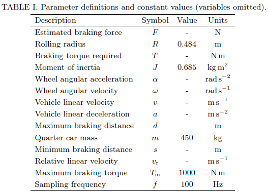
Table I and equations (1)-(5) provide all of the information required for calculation of the required braking torque T, based upon the analogue sensor input of angular velocity ω and distance of obstruction d. Results from your test calculations can be compared with FIG.2. The warning signal logical conditions use the constant Tm plus equations (6) and (7).
The equation of motion for the estimated braking force of a quarter car model is
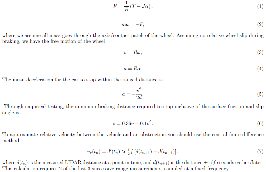
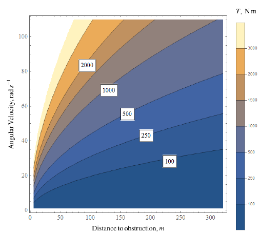
FIG. 2. Braking torque required on the wheel for the expected ranges of angular velocity and distance.
III. SPECIFICATION
An encoder is connected to P5.1 on the C167. The sensor has an on-board routine to return an linear angular velocity range of 0 → 110 rad s−1 for a voltage output of 0 → 5V.
A LIDAR is connected to P5.2 on the C167. The sensor provides linear distance ranging of 5 → 320m with a voltage output of 0 → 5V.
A digital input line from the AEB controller is connected to P2.15 on the C167. All outputs should be set low while this line is low. The program waits for this signal to be high before doing any actions.
8 digital output lines are connected from P2.0, to P2.7 on the C167 that go to an external 8-bit DAC. When P2.15 is low, all digital output lines should all output a low logic level. A braking torque of 1000Nm should output 0xFF across the digital output lines, with P2.7 being the most significant bit and P2.0 the least significant bit. A braking torque of 0Nm should output 0x01 across the digital output lines.
If
• the braking distance required to stop s is greater than the current value measured by the LIDAR d and the relative velocity vr is negative, or
• the braking torque required to stop T is greater than the maximum braking torque Tm and the relative velocity vr is negative,
then the microcontroller should send a warning signal to the AEB controller over digital output P2.11 on the C167. This signal should be high when s > d or T > Tm in combination with vr < 0. When P2.11 is high, lines P2.0, to P2.7 should return 0x00.
The relative velocity between the vehicle and an obstruction should be calculated at 100 Hz, that is, Δt = 0.01s = tn+1 − tn.
P2.11 should remain outputting high for 4 seconds, before being set to low and the conditions recalculated/updated. Your boss has suggested that even though the microcontroller outputs digital values, you should have a way to view the floating point torque value within the simulator. This result should be shown when checking the digital output signals.
The sensors are assumed to never encounter a failure or read error. The sensors saturate their outputs high/low if the data is outside of range.
REPORT STRUCTURE
You report is to be structured as below.
• Introduction - What are you doing? Why are you doing it?
• Specification - How are you doing it? Capture all details from the theory and specification sections of this assignment sheet.
• Assumptions - What are you assuming in order to complete this task? Are there any limitations in the C implementation or the digital system? Assumptions with the theory?
• Conceptualisation - High and low level flowcharts & optional pseudo-code
• Implementation - What are your modules? What does each do? What registers/peripherals are you using? A UML diagram.
• Operation - Screenshots of your program outputs at each stage of your flowchart. Demonstrate the functionality of your code with simulated inputs for all output states.
• Discussion - Are there any limitations to this program? Are there any changes you would make? Is your program lacking functionality?
• Conclusion - Did you complete the project? How did you complete it? Are there any notable outcomes? How extensible is your solution?
Students succeed in their courses by connecting and communicating with an expert until they receive help on their questions

Consult our trusted tutors.


 Login | Sign Up

