Task:
Your task is to program the PLC code for a tree orchard and irrigation system at the Quiet Gully Tree Farm.
The details of the system are given below. The code is to be programmed in Ladder language using the template file provided. The preferred version of software is ZelioSoft 2 v5.4.0
Hardware
The Zelio relay used is the SR3B261B with a digital I/O expansion module SR3XT101B. These are all pre-configured in the provided template.
Provided Diagrams
Refer to the provided Piping and Instrumentation Diagram (Drawing ELE1301-S1-22-P&ID) and Site Plan (Drawing ELE1301-S1-22-SITE_PLAN). The site plan is provided to give context to the irrigation system, it is NOT TO SCALE and is not to be used for any technical purpose.
System Overview
There are 4 Orchards and 2 Nursery Zones. The irrigation requirements are different for the normal Orchards, where trees are more mature, and the Nursery Zones, where young seedlings are grown. The most obvious difference is that there are sprinklers in the Orchards and misters in the Nursery Zones. The Orchards are watered one at a time, at either low or high flow, but the nursery zones are always misted together at the same time at low flow. For this reason, the nursery zones share a supply valve.
The sequence of operation is described later in this document.
Water Supply
The water is supplied by the “Water Supply System” (WSS) which has its own control system which ensures a steady supply to the irrigation system from the mix of bore and tank water storage on site. The details of this are out of scope except for the PLC interface between the Irrigation System and the WSS. The irrigation system will request water supply, either at low or high flow. The WSS will indicate when it is supplying water (active) or if the WSS is currently unavailable due to a fault.
Flow Alarms
There is a flow switch on entry to the system, which will trigger an alarm if there is no flow for 10 seconds after the Water Supply Active signal comes from the WSS. It might not be obvious how this situation can occur, but suppose the WSS is nominally supplying water to the irrigation system, however due to a broken pipe between the WSS and irrigation system, very little of that water is actually passing through the entry flow switch.
Each line has a flow switch, which will trigger an alarm if there is no flow for 10 seconds after it has been confirmed that the associated line valve has opened and the main flow switch has indicated flow.
Valve Alarms
All valves have both open and closed position feedback and the program should include alarm logic for both opening and closing a valve. Since a valve can get stuck midway between open and closed positions, separate open and closed indications are required. It may be assumed that the valves will normally require no more than 5 seconds travel time to switch between fully open and fully closed, or vice versa.
Input Debouncing
The 6 flow switch inputs shall be explicitly debounced for a suitable duration. Each flow switch input shall use a separate debounce timer.
Your solution may also debounce other inputs for a suitable duration (the required duration depends upon the nature of the input) if you have enough timers available, but this is not mandatory, and you will not lose marks for not debouncing inputs which are not flow switches. Each input which is explicitly debounced shall use a separate timer.
Inputs which are not explicitly debounced can use the in-built slow hardware input filtering (see Edit > Program Configuration > Configuration), which is already enabled in the template, in lieu of explicit timer based debouncing.
Visual Outputs
All alarms are to be latched and reset only by the Alarm Reset Pushbutton.
There is an alarm light output to indicate an alarm condition, and an alarm reset pushbutton to clear alarms. Your solution may use different flashing patterns on the alarm output for different alarms to aid in alarm identification if you have enough timers available, but this is not mandatory. and you will not lose marks for using the same alarm output for all alarm types.
There is also a light output which indicates when the system has been turned on, and a light output which indicates when the system is running (i.e. irrigating).
Operation
The Irrigation System begins operation when the On Switch is on, no alarms are active in the Irrigation System or the WSS and the Start Cycle Pushbutton is pressed.
The irrigation system is programmed to water one Orchard, or both Nursery Zones, at a time. Each area will be watered for 20 seconds.
You will determine a sequence for the irrigation using the following method, and then implement this sequence in your PLC code. Roll a 6-sided dice to determine which is the irrigation target. If the number rolled is between 1 and 4 inclusive, enter this Orchard into the Irrigation Target column. If the number rolled is a 5 or a 6, enter the Nursery Zones into the Irrigation Target Column. Once a number has been rolled, it cannot be entered a second time into the table. Therefore, if the sequence of dice rolls is 3, 4, 3, 1, 6, 6, 4, 3, 5, 2, then deleting repeats, the sequence is 3, 4, 1, 6, 5 and 2. The entries into the Irrigation Target column from step 1 to 6 would then be Orchard 3, Orchard 4, Orchard 1, Nursery Zones, Nursery Zones and Orchard 2.
For the Orchards, flip a coin to determine if the flow should be High or Low Flow. The Nursery Zones will always be Low Flow.
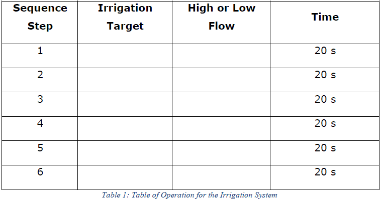
Table 1: Table of Operation for the Irrigation System
Once the irrigation system has completed one cycle of 6 steps, it returns to idle and waits for the Start Cycle Pushbutton to be pushed again.
A summary of the system inputs and outputs is as follows.
Digital Inputs
I1: V001 Open Indication
I2: V001 Closed Indication
I3: V002 Open Indication
I4: V002 Closed Indication
I5: V003 Open Indication
I6: V003 Closed Indication
I7: V004 Open Indication
I8: V004 Closed Indication
I9: V005 Open Indication
IA: V005 Closed Indication
IB: FS001 Flow Indication
IC: FS002 Flow Indication
ID: FS003 Flow Indication
IE: FS004 Flow Indication
IF: FS005 Flow Indication
IG: FS006 Flow Indication
IH: X001 On Switch
IJ: X002 Start Cycle Pushbutton
IK: X003 Alarm Reset Pushbutton
IL: X004 Water Supply Active
IN: X005 Water Supply Fault
IP: N/A
Digital Outputs
Q1: V001 Open Command
Q2: V002 Open Command
Q3: V003 Open Command
Q4: V004 Open Command
Q5: V005 Open Command
Q6: Y001 System On Light
Q7: Y002 System Running Light
Q8: Y003 Alarm Light
Q9: Y004 Water Request
QA: Y005 High Flow Request
The input HV001 on the Piping and Instrumentation Diagram is a hand valve and so not controllable by the PLC software.
Report:
You must submit a report that meets the following minimum objectives:
• An overview of the operation of the system. This should include the table of operation for the given irrigation sequence (see Table 1 above).
• Documentation of assumptions or clarifications around the task (if any).
• A brief Functional Specification. This means that for each item (that is part of the PLC system), you will provide a short (1-3 sentence) description of the required operation, impact on other equipment and any alarms related to that device.
• A timing chart showing the normal operation of the plant from being turned on and receiving the start cycle command, to running through the Irrigation Sequence you have determined for your system and returning to idle state. Note that you do not need to include alarm events in this timing diagram since it only represents normal expected operation. Actions which occur within a few ms of each other can be represented at the same time on the timing chart.
• Description and documentation of the code structure, along with any variables, timers, counters or other capabilities used.
• Screen shots of two cases showing the code window and supervision window (with I/O visible) in simulation mode as follows:
(i) The system during the 4th Sequence Step
(ii) A valve failing to open during operation
• Documentation of the testing process undertaken and the full results of the testing process. The presentation of this data is up to you but it should be thorough and logical. You might use a timing chart.
• A 3-4 minute video recording (mp4 file, maximum size 100 MB) explaining how your code works, and demonstrating the operation. (Hint: Use Zoom with screen share and record your session. Please include your own video image as an inset.)
Students succeed in their courses by connecting and communicating with an expert until they receive help on their questions

Consult our trusted tutors.


 Login | Sign Up

