Goal
To demonstrate your C programming and programme design skills through development of a non-trivial robotic system.
Introduction
This is a Team Project – you will work in pairs. Your team is required to design and build the software for a robotic vehicle. You will develop your system using the online circuit simulation tool at tinkercad.com and then once working load your programme onto the robotic vehicle. You will need to create an account in Tinkercad before you can use their circuit simulator.
The Tinkercad simulator allows for many common electronic components including the Arduino Uno. The Arduino Uno is a development board for the ATMega328P microcontroller (think of this as a mini computer that you can run just one programme on). You will be writing C code to programme the Arduino, but you are not expected to change or fully understand the hardware components.
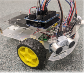
Robot Hardware Overview
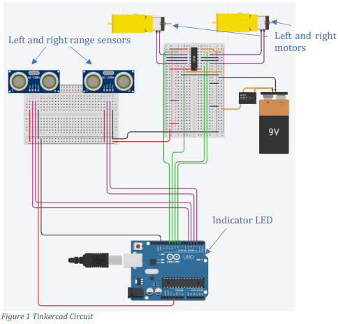
The robot consists of 2 active wheels, one passive wheel, two range sensors, a battery, an indicator LED.
Wheels
There are 2 wheels; to steer left, the right wheels should turn forwards and the left wheels backwards. To steer right, the left wheels should turn forwards and the right wheels backwards.
There are two Arduino pins used to control each wheel: Pins 10 and 11 for the left wheel and pins 8 and 9 for the right wheel. To go forwards set the pin with the larger number HIGH and the pin with the lower number LOW. To go backwards set the pin with the lower number HIGH and the pin with the higher number LOW.
Range Sensors
The range sensors measure distance by sending out an ultrasonic pulse. They then create an echo pulse in response, the duration of this pulse is proportional to the distance:

where d is the distance in centimetres and t is the pulse length in microseconds.
To trigger the pulse, set the trigger pin to HIGH for 10us. Hint, you can use the delayMicroseconds function. The left range sensor’s trigger is connected to pin 5 and the right range sensor’s trigger is connected to pin 3.
The echo pulse can be read using the Arduino pulseIn function. The left range sensors echo is connected to pin 4 and the right range sensor’s echo is connected to pin 2.
Indicator LED
The indictor LED can be turned on by setting pin 13 to HIGH and turned off by setting pin 13 LOW.
Motor Encoders
There are special discs with slots in them attached to each motor. When the wheels turn the slots pass by an LED and Photodiode which sends a pulse (e.g. a HIGH followed by a LOW) each time the slot passes the LED. There are 20 slots in each disc, so you can detect how many times the wheel turns by counting how many pulses are sent to the Arduino.
The left motor encoder is attached to pin 6 and the right motor encoder is attached to pin 7.
Software Requirements
You must design and build a programme for the ATMega328P on an Arduino Uno R3. The programme will be used to control a robot, the hardware of which will be provided to you (only the software design and implementation is in scope for this assignment). Your programme must meet the following requirements:
• Drive continuously in a square approximately 1m on each side unless an obstacle is encountered.
• Read the left and right distances from the two range sensors and steer away from any detected obstacle.
• When an obstacle is encountered, turn the indicator LED on; leave it off otherwise.
Programming and Simulation
Once you have designed your programme you can start to write the code in Tinkercad. The hardware has already been setup for you, so you can just make a copy and tinker away: https://www.tinkercad.com/things/abzpuBaAZ3G?sharecode=yhIgFBGHsaVszW9eRwK5X8B0 aId1Ai8D6nakGqWC_dI. You are not expected to make changes to the hardware.
Once you can demonstrate that the programme works in Tinkercad you can load your programme onto the robot using the Arduino IDE.
Note that there are some limitations in Tinkercad, for example there are no motor encoders in
Tinkercad, so you will not be able to use them in the simulation. Use of the encoders is optional,
however if you can use the encoders to more accurately drive in the 1m square.
Students succeed in their courses by connecting and communicating with an expert until they receive help on their questions

Consult our trusted tutors.


 Login | Sign Up

