This is an exercise in designing combinational circuits that can perform binary-to-decimal number conversion and binary-coded-decimal (BCD) addition, using Proteus Design Suite.
Part I
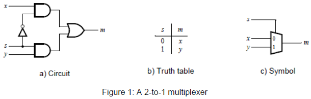
Figure 1a shows a sum-of-products circuit that implements a 2-to-1 multiplexer with a select input s. If s = 0 the multiplexer’s output m is equal to the input x, and if s = 1 the output is equal to y. Figure 1b gives a truth table for this multiplexer, and part c shows its circuit symbol.
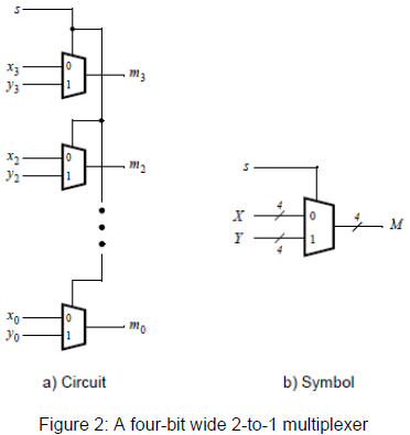
You are to use four instances of the circuit shown above to create the circuit given in Figure 2a. This circuit has two four-bit inputs, X and Y, and produces the four-bit output M. If s = 0 then M = X, while if s = 1 then M = Y. We refer to this circuit as a four-bit wide 2-to-1 multiplexer. It has the circuit symbol shown in Figure 2b, in which X, Y, and M are depicted as four-bit wires.
Students succeed in their courses by connecting and communicating with an expert until they receive help on their questions

Consult our trusted tutors.


 Login | Sign Up

