Part II
You are to design a circuit that converts a four-bit binary number V = v3v2v1v0 into its two-digit decimal equivalent D = d1d0. Table 1 shows the required output values. A partial design of this circuit is given in Figure 3. It includes a comparator that checks when the value of V is greater than 9 and uses the output of this comparator in the control of the 7-segment displays. You are to complete the design of this circuit.
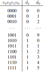
Table 1: Binary-to-decimal conversion values.
The output z for the comparator circuit can be specified using a single Boolean expression, with the four inputs v3 = v0. Design this Boolean expression by making a truth table that shows the values of the inputs v3 = v0 for which z must be 1.
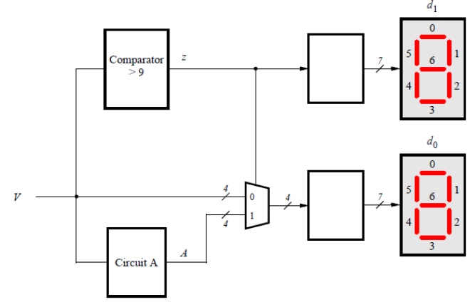
Figure 3: Partial design of the binary-to-decimal conversion circuit
Notice that the circuit in Figure 3 includes a 4-bit wide 2-to-1 multiplexer. The purpose of this multiplexer is to drive digit d0 with the value of V when z = 0, and the value of A when z = 1. To design circuit A, consider the following. For the input values V ≤ 9, circuit A does not matter, because the multiplexer in Figure 3 just selects V in these cases. But for the input values V > 9, the multiplexer will select A. Thus, A must provide output values that properly implement Table 1 when V > 9. You need to design circuit A so that the input V = 1010 gives an output A = 0000, the input V = 1011 gives the output A = 0001, . . ., and the input V = 1111 gives the output A = 0101. Design circuit A by making a truth table with the inputs v3-0 and the outputs A3-0.
Students succeed in their courses by connecting and communicating with an expert until they receive help on their questions

Consult our trusted tutors.


 Login | Sign Up

