Be Prepared For The Toughest Questions
Practice Problems
EXERCISE 1 – ANNUNCIATOR
In industry, plant conditions are monitored and, if there are problems, it is necessary to have some way of indicating such problems. An indicator system of this type is called an Annunciator. A typical alarm system uses the following sequence to indicate a plant alarm condition to an operator.
(i) System healthy – no indication.
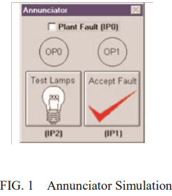
(ii) System in alarm – a flashing Amber light and audible alarm. FIGURE 1 shows the graphics simulation of the alarm system.
1. If the operator presses the ACCEPT button when the plant is in alarm (ii above), the audible alarm stops and the flashing Amber light changes to permanently ‘ON’.
2. If the plant drops out of the alarm condition before the ACCEPT button is pressed, the panel will show a flashing Green light. The Audible alarm and Amber light will go ‘OFF’.
3. If the ACCEPT button was pressed when the plant is healthy as in 2 above, the flashing Green light will go ‘OFF’.
4. There should be a LAMP TEST button which, when pressed, will light all lamps and sound the audible alarm.
5. Write a program that will operate the Alarm Simulation, using the following inputs and outputs and whatever Timers and Flags are required.
IP0 = Plant alarm condition OP0 = Amber Lamp
IP1 = Operator accept button OP1 = Green Lamp
IP2 = Lamp test OP2 = Audible Alarm
6. Use the comments facility to describe the operation of the program.
Know the process
Students succeed in their courses by connecting and communicating with
an expert until they receive help on their questions

Unable to find what you’re looking for?
Consult our trusted tutors.


 Login | Sign Up


