Part 1.4 Coordinating Distance Relay Protection on Line 9-5
Criteria for Coordination of Three-Zone Distance Relay Scheme: Fundamentally, distance relays compare the power system voltage and current.They operate when the ratio V/I is less than the pre-set value. For balanced conditions and for all types of phase faults, the ratio of the voltage to the current applied to the relay is the impedance of the circuit. Thus, the relays are set as a function of the fixed impedance of the power system for the zone they are to protect.
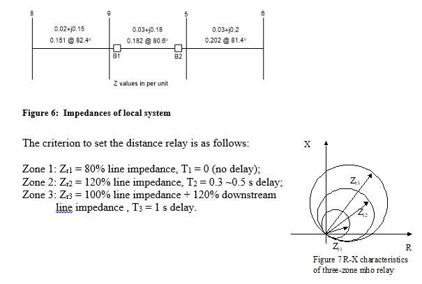
The characteristics of the distance relay is most conveniently shown on an impedance R-X diagram with the resistance R plotted along the x-axis and the reactance X plotted along the y-axis. The most commonly used distance relay is the three-zone mho relay shown in Figure 7. The larger numbered zone covers a larger range but with a longer delay time before operation.
Task 4. Selecting CB, CT’s and PT’s for breaker B1.
a. Determine maximum fault current through the circuit breakers at bus 9. (Fault current through the breaker, not fault current into the fault)
(Etc.)
Determine maximum continuous current in Line 5–9:
Advice: Maximum continuous current of the overhead line is determined by the conductor rating. Add 10% for overload possibility. (Etc)
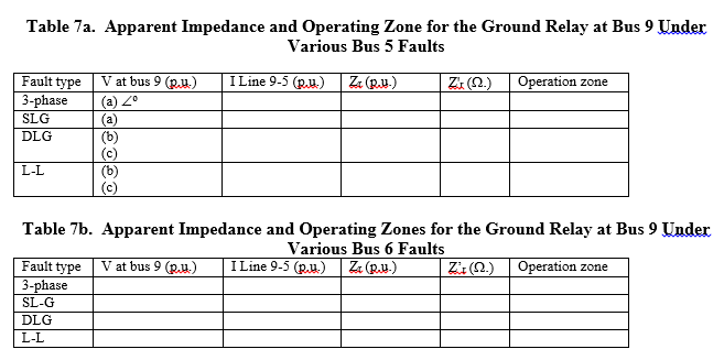
To validate the initial settings of the previous section, you will need to calculate Zactual for each type of fault. Calculate Zactual observed in per unit at Bus 9 for faults at busses 5 and 6 and fill in the tables below. Calculate Zactual observed for the following fault types: 3 phase, SLG, L-L and DLG.
Hint: You’ll need to find I(9-5) line currents under these fault conditions, NOT the current into the fault. You can do this by left clicking on a bus, choosing Fault Analysis, and the choosing the Lines Tab under the Fault Data Tab.
Remember that your relay need respond to only the faulted phase(s) during a fault and this (these) phase(s) will be the one(s) experiencing the fault. For a 3-phase fault, Zactual of only one phase needs to be calculated and checked against initial setting as the fault is symmetrical; for SLG, DLG and L-L faults, the faulted phases need to be checked to ensure that the impedance seen for these phases falls into the operation zone.
(Etc.)
Task 6b. Adjustment to the reach of ground relays:
After examining all fault types, you must set ground relays to protect against the ground fault with the largest impedance. When you set the ground fault relay according to Zactual, you may find that the relay overreaches for the other faults. This will lead to tripping for distant faults. There is a unit that supervises the ground fault relays (known as a ground current device), which only allows them to operate under ground fault conditions. You may wish to invoke the ground current device to “supervise” your ground fault relay and avoid unwanted tripping.
Noticing that for a SLG, the apparent impedance seen at B1 for a fault at bus 6 is beyond the reach of the distance ground relay…. Etc.
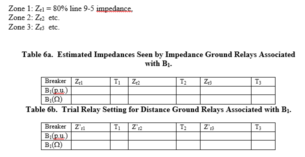
Zone 1: Zr1 =
Zone 2: Zr2 etc.
Zone 3: Zr3 etc.
Make a sketch indicating zones of protection and draw mho relay operating region diagram in R-X plane showing magnitude and angle of the settings in a scaled diagram similar to Figure 7.
Task 7a: Finding Zactual at bus 9 for faults at busses 5&6 for phase impedance relay
To validate the initial settings, you will need to calculate Zactual for each type of fault. Calculate Zactual observed in per unit at Bus 9 for faults at busses 5 and 6 and fill in the tables below. Calculate Zactual observed for the following fault types: 3 phase, SLG, L-L and DLG.
Remember: You’ll need to find I(9-5) line currents under these fault conditions, NOT the current into the fault.
Remember that your relay need respond to only the faulted phase(s) during a fault and this (these) phase(s) will be the one(s) experiencing the fault.
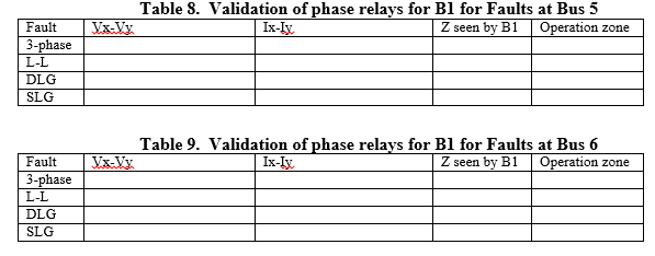
In addition to ground relays, phase relays are used to protect transmission lines. The impedances seen for each fault type for the phase relays are shown in Tables 8 and 9. The initial settings for the phase relays were taken to be the same as the original distance relay settings give in Table 6. Next the performance of the phase relays for controlling B1 for each type of fault was evaluated. Etc.
Set phase relays to protect against phase faults: 3-Phase, L-L and DLG.
(Etc.) (If necessary.) These relays should be set to protect for faults that the ground fault relay will not protect against. Comment on whether there is beneficial redundancy in your settings. For example, are there some faults that are detected by both types of relays, even if they may not be in the appropriate zones of protection.
Draw the mho relay operating region diagram in R-X plane showing magnitude and angle of the settings in a scaled diagram similar to Figure 7.
Students succeed in their courses by connecting and communicating with an expert until they receive help on their questions

Consult our trusted tutors.


 Login | Sign Up

