Part 1.2 Modeling the system using PowerWorld and validating the model.
Task 0: Modeling the Radial Line:
The first step is to find the impedance/length for the distribution feeder of Figure 4.
And then convert the impedances into the appropriate per unit system.
Hint: Choose the low temperature resistance for conductor to be conservative.
Reminder: Your positive and negative sequence impedances are equal.
Reminder: The zero sequence impedance for this line is 3 times the positive sequence impedance. (This 3-to-1 ratio only applies to this line and is an approximation since we haven’t learned how to calculate zero sequence values with a ground conductor and earth return.)

Task 1. Modeling the system using PowerWorld
Set up the positive and zero sequence systems in the PowerWorld software so that maximum and minimum fault current magnitudes can be calculated.
Remember: Xd’’ is machine positive and negative sequence impedance.
First get all generators impedances in per-unit using the same base system. Fill in the table below.
To complete the model, the transformer impedances were converted to a consistent per-unit system as shown in Table 2b.
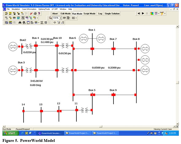
These values were used, along with the transmission line values of Figure 2 to build the model using the PowerWorld Simulator as shown below. (Include a figure of your PowerWorld schematic. DO NOT use mine in your report.)

Validation
Explain what you did to validate your model. Use the tables below to compare your results with the fault values from a model that is known to be valid. All values in the table below are phase a values, except where noted. E.g., (14b) below means bus 14 phase b. The values for the branch current flows provided below are currents flowing in the direction of the arrow, e.g. from bus 8 to bus 9 for the three-phase fault on bus 5. PowerWorld lists line current flow as away from each bus. Depending on the order in which you constructed your model, bus 8 may be a “FROM” bus or a “TO” bus. Hence, to match my phase angle values for the bus 5 fault, you may need to looking at “Phase Ang A TO” or “Phase Ang A FROM.” Depending on how you rounded off your parameter values, your values may not match mine exactly, but they should be within 1%.
*XT=0.12 on a 60MVA, 230 kV base
** The value I give is the current flowing from the grounded-wye side of the transformer. (Note that the “line” current into the delta should be less than the current on the wye side since no zero sequence current can flow into the delta side.)


