Part 1.1: Problem Statement
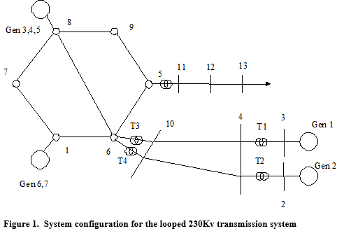
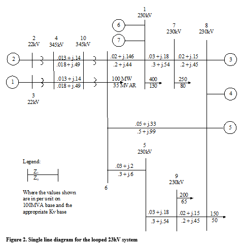
The topology of the 14-bus system this project is based upon is shown in Figure 1. This figure represents a diagram of an Arizona looped 230kV transmission system. This is a typical system configuration for serving a large city. Figure 2 is the single line diagram of the 230kV and 345kV systems that shows the series impedance values. (Per unit values shown in Figure 2 use an MVA base of 100 MVA, and voltage bases of 230kV and 345kV at appropriate places within the system.) Notice that remote generation is input to the loop via two 345kV lines. The voltage is transformed from 345kV to 230kV by three-phase transformer banks T3 and T4. Transformers T1 and T2 step the voltage up at the remote generating site. The transformer data for this system follows:
Transformers:
Transformers 1 and 2 are 3-phase rated at 350 MVA, 22kV delta to 345kV grounded wye, 8% reactance;
Transformers 3 and 4 are 3 phase rated at 400 MVA, 345 kV grounded wye to 230 kV grounded wye, 6% reactance.
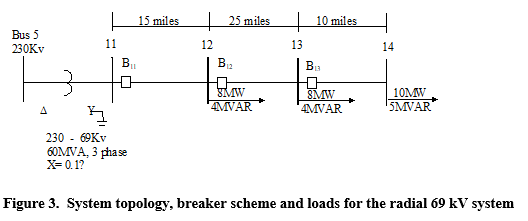
In addition to the 230 kV – 345 kV system shown above, we will need to coordinate overcurrent protection of the 69 kV system whose topology is shown in Figure 3.
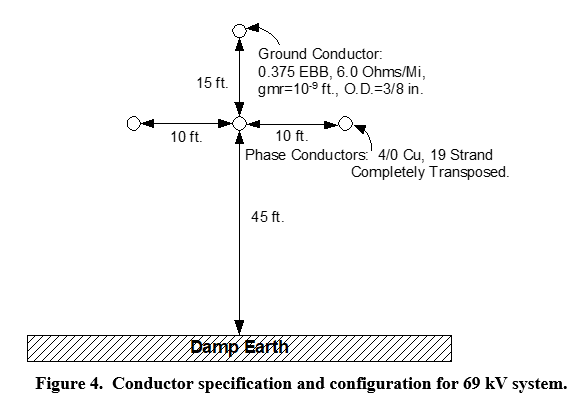
The conductor specifications and configuration for this 69 kV system is shown in Figure 4.
Students succeed in their courses by connecting and communicating with an expert until they receive help on their questions

Consult our trusted tutors.


 Login | Sign Up

